Address
Blyth, Northumberland
U.K. NE24 2QW
Telephone
+44(0)1670 336766
Opening Hours
Monday to Friday: 08:00 - 17:30
Address
Blyth, Northumberland
U.K. NE24 2QW
Telephone
+44(0)1670 336766
Opening Hours
Monday to Friday: 08:00 - 17:30
We don’t treat wiring as an afterthought. This post explains how combining AutoCAD Electrical with Inventor’s Cable & Harness tools lets us design harnesses in 3D, cut errors, and deliver build‑ready digital twins.
Complex electric and hybrid machines live or die on their wiring. A single mis‑routed harness can take down a prototype, delay builds and create intermittent faults that are almost impossible to trace once the machine is in the field. Traditional 2D drawings and scribbled routing notes simply don’t cope well with dense, high‑voltage, multi‑ECU harnesses snaking through tight packaging.
That is why we treat 3D harness design as part of the machine design, not an afterthought. AutoCAD Electrical handles the logical connectivity; Autodesk Inventor’s Cable & Harness environment handles the physical reality of where the wire actually goes, how long it is, and what it has to clear on the way.
The first step is always the schematic. AutoCAD Electrical (or equivalent) captures:
That connectivity is then exported as a wire list (CSV/XML) and pulled into Inventor’s Cable & Harness environment. From there, the harness is designed directly inside the 3D assembly of the machine.
Key benefits of doing it this way:
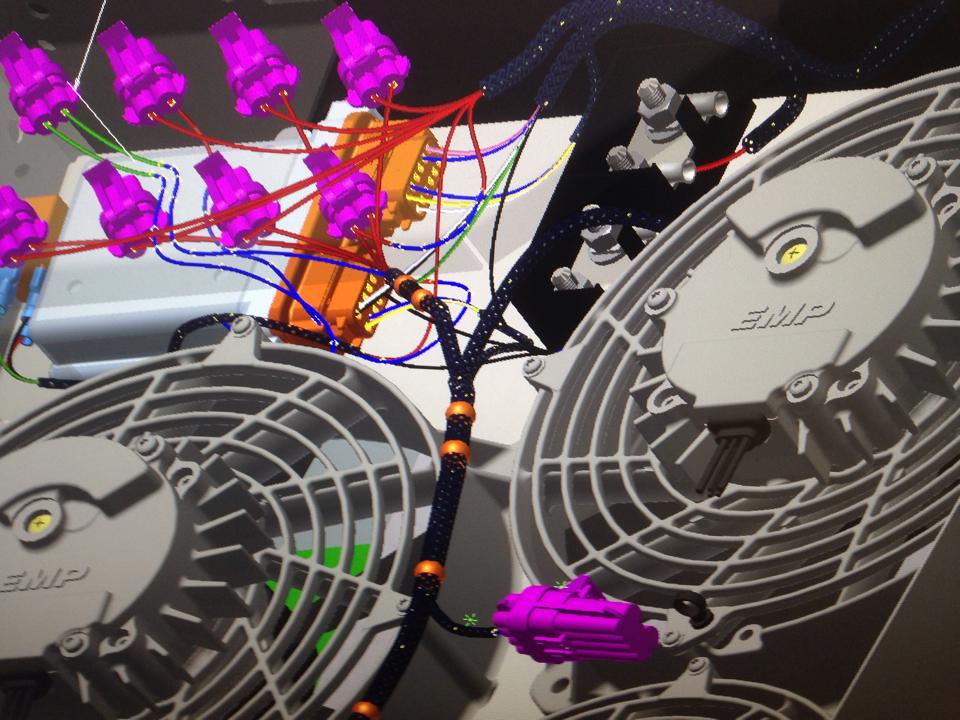
Inventor’s intuitive harness tools let you define 3D paths (segments) that follow the actual machine structure – along chassis rails, through bulkheads, around sharp edges, across moving joints.
Advantages this gives over 2D:
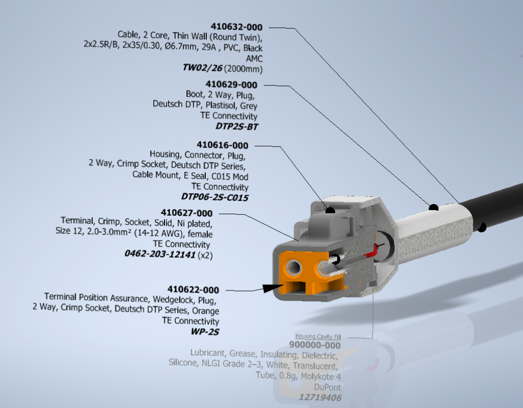
For the shop floor, that means cut lists, BOMs and nailboard drawings are generated from a harness that has already been test‑fitted virtually. For the design team, it means later geometry changes – a moved bracket, a new cooling line – push straight through to the harness model instead of being discovered by a confused harness tech months later.
On high‑voltage and safety‑critical systems (800 V traction, HVIL, safety‑related I/O), 3D harness design stops being a convenience and becomes a safety tool:
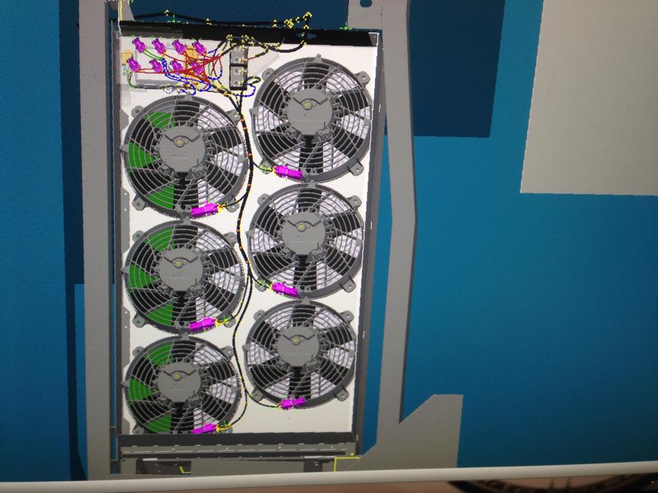
The result is fewer surprises on prototype builds, less rework in production, and a harness set that is documented as a digital twin, not just a stack of 2D drawings and tribal knowledge.
All of this runs on an Autodesk toolchain: AutoCAD Electrical for schematics and Inventor Cable & Harness for 3D routing, managed inside an Autodesk Vault environment so models, harness data, BOMs and drawings stay under proper revision control. The work is supported by the Autodesk Foundation’s Technology Impact programme, which provides software donations to organisations using design and engineering to tackle environmental and social challenges – exactly the space our zero‑emission machinery sits in.